
The Data Center Went DC. The Model Didn't.
AI racks are dragging power distribution from AC to 400 and 800 volts DC. The single-line drawings, twins, and management tools we plan and protect the plant with were built for a topology on its way out.
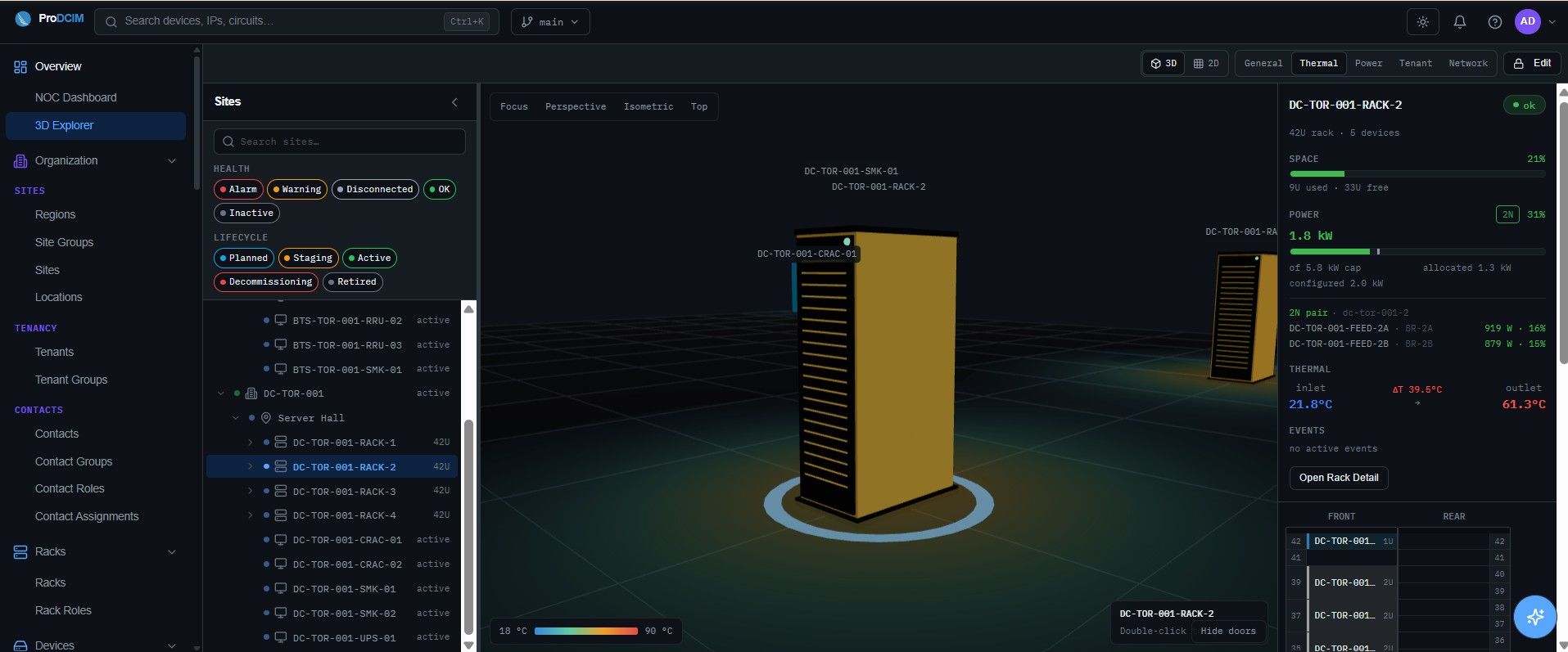
Somewhere in your organization there is a picture of the power chain: a single-line drawing, a DCIM topology, a digital twin. It shows a sequence that has been correct for thirty years: utility feed, transformer, UPS, distribution, PDU, and a power supply in every server quietly turning AC into the low-voltage DC the silicon actually runs on. For the racks now going in to feed GPUs, that picture is starting to describe a plant that is disappearing.
The shift is not cosmetic. A megawatt-class AI rack cannot be fed the old way without absurd amounts of copper, and the industry's answer is to stop distributing AC to the rack at all. That single decision changes what the equipment is, how it fails, and how it must be protected, which means it changes what your model has to represent. Most models have not caught up, and the gap is quiet, because a drawing of the wrong plant still looks like a drawing.
Why the rack is abandoning AC
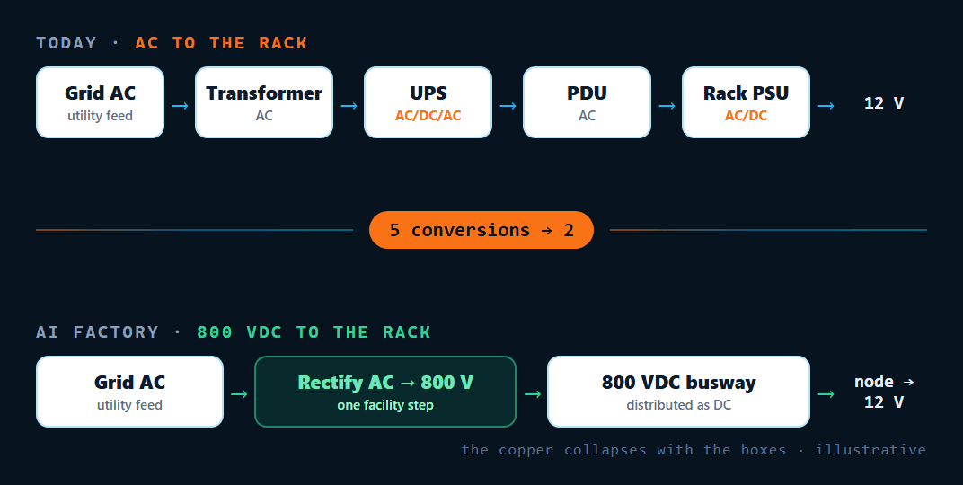
The math is blunt. Delivering hundreds of kilowatts to a rack at 48 volts means moving thousands of amps: a single one-megawatt rack on legacy low-voltage distribution can call for on the order of 200 kilograms of copper busbar. Raise the distribution voltage and the current, the copper, and the cabling all fall away, and you shed conversion stages in the bargain. That is why the direction of travel is high-voltage DC: distribute at hundreds of volts DC across the facility, then do one late, high-ratio step-down right next to the processor.
The ecosystem is converging on two variants of the same idea. One camp runs a bipolar arrangement at roughly ±400 V, chosen deliberately to reuse the mature electric-vehicle supply chain: the same class of transistors, capacitors, and connectors. The other pushes to 800 VDC to feed the very densest racks. Both replace a chain of AC conversions with a single facility-level rectification step and DC all the way to the node.
The model was built for a topology that's leaving
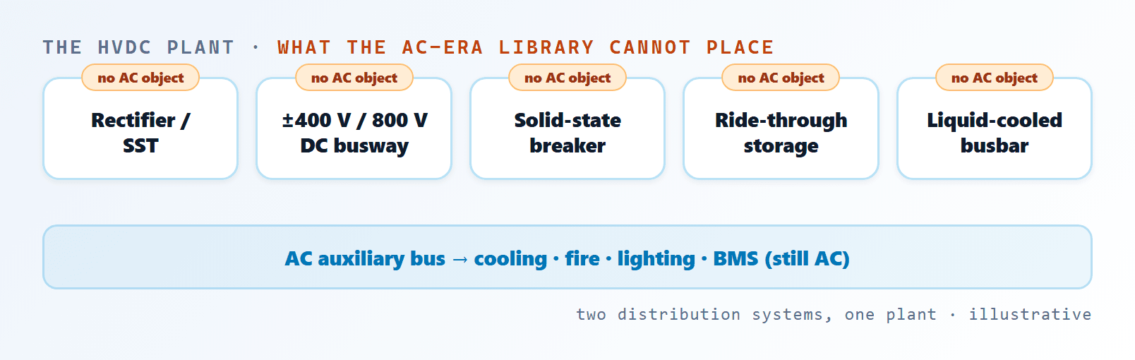
A DCIM tool or a twin is only as good as its object library and the physics behind it. The AC-era library knows transformers, UPS systems, AC PDUs, and per-server power supplies. The HVDC plant introduces a set of things that library has no representation for at all:
- DC distribution. A ±400 V bipolar or 800 VDC busway is not an AC feeder with a different label. Its losses, ampacity, and behavior are different, and increasingly the busbar is liquid-cooled.
- Solid-state protection. DC does not cross zero, so protection is electronic rather than a tripping breaker: a different device with different coordination and different failure behavior.
- Multi-timescale energy storage. Supercapacitor and battery ride-through are now inline to absorb sub-second GPU power swings, an active element the static model never contained.
- The retained AC bus. Cooling, fire suppression, lighting, and building management still run on AC, so the plant is now genuinely hybrid: two distribution systems that must be modeled together.
If a tool cannot place a DC busway, a solid-state breaker, or a bipolar rail on the diagram, it cannot compute losses, fault current, or energy flow for the plant you actually built. It will happily give you an answer. The answer will be for a facility that no longer exists.
DC changes the failure modes, not just the wiring
This is where an out-of-date model stops being a documentation problem and starts being a safety and reliability problem. Direct current does not have the natural zero-crossings that AC protection relies on, so fault interruption works differently. Bipolar distribution introduces ground-fault behavior that has no analogue on a three-phase AC feeder. And because inline storage is now actively shaping power during GPU transients, the plant's dynamic response is part of its protection story. A model that silently assumes AC fault coordination will give confident, wrong answers about exactly the events you most need to get right.
Standards lag, so every build is bespoke
The codes are visibly racing to catch up, and busway standards have only recently been extended toward and past the kilovolt-DC range, but certification paths for much of this equipment are still thin. In practice that means each installation is a custom engineering exercise, qualified and approved case by case rather than dropped in from a settled reference design. Bespoke plants make an accurate, per-site model more valuable, not less, because there is no standard drawing you can safely assume applies.
What it takes to manage a DC plant
Solving this is not a matter of adding a few DC labels to an AC tool. It takes three things working together. First, the model itself has to be rebuilt around the new topology: DC busways, converter and rectifier chains, solid-state protection, bipolar rails, inline storage, and the retained AC auxiliary bus all present as first-class objects with the right physics, not as AC components wearing DC values. Second, that model has to be fed live DC-side telemetry (rail voltages, converter and busbar temperatures, storage state of charge, protection events) and be able to simulate energy flow, losses, and fault propagation on the DC topology, not just display readings on it. Third, because the builds are bespoke, it has to be maintainable per site rather than assumed from a template.
Put plainly: operating an HVDC data center safely and efficiently requires DCIM and digital-twin software whose data model and simulation engine actually understand high-voltage DC. An AC-era tool with DC numbers pasted into AC objects will keep producing tidy diagrams of the plant you used to have. The organizations moving to DC distribution need their model to move with it, or they are flying the most demanding facilities they will ever run on an instrument that describes a different building.
See it on your own racks
Book a walkthrough mapped to your environment: monitoring, asset management and out-of-band resilience across every site.
More insights

Why does it take so long to find the equipment behind an alert?
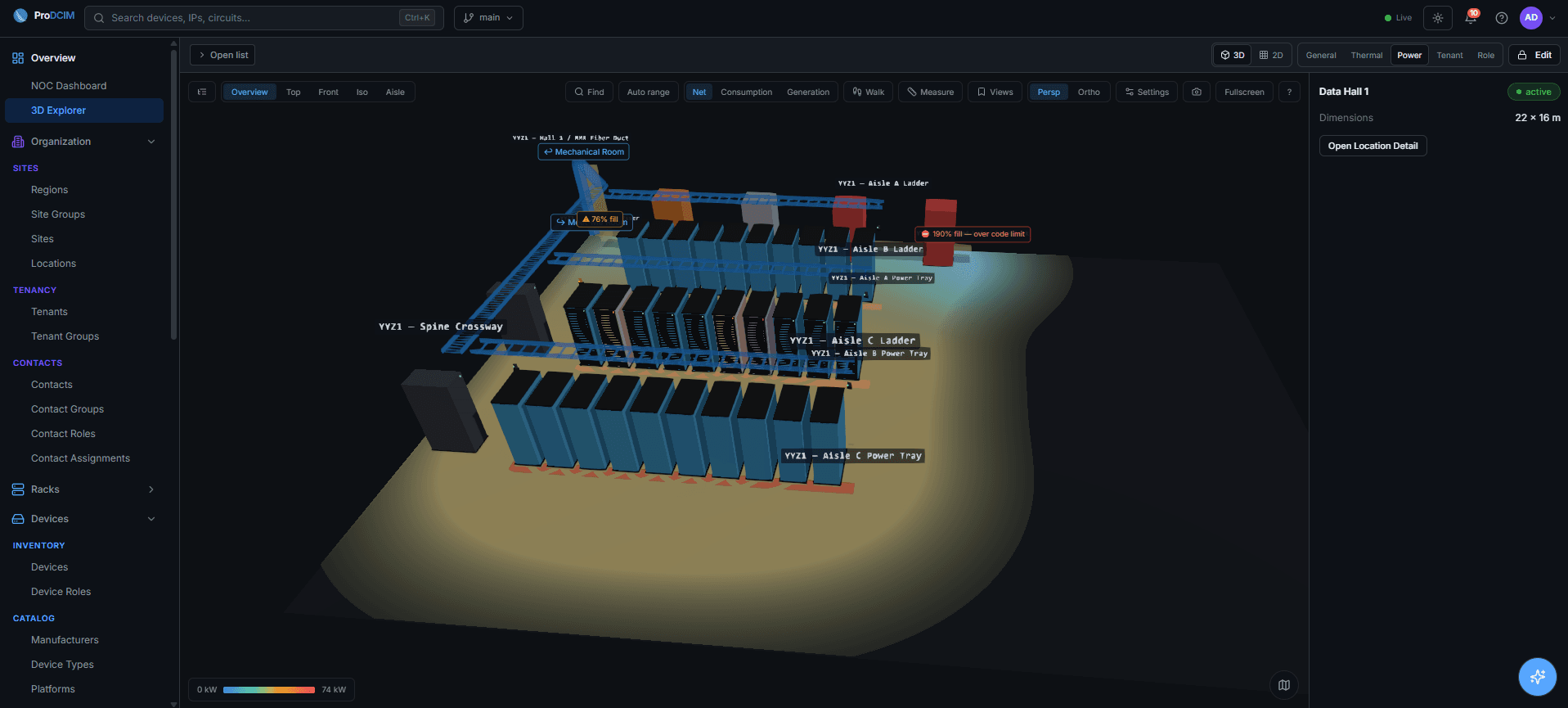
A PDU circuit crossing 80 percent names a circuit, not a device. When the floor plan, the asset register and the power readings live in separate systems, closing that gap is the slowest part of the shift. Here is what changes when they share one model of your infrastructure.
Racks Are Getting Denser. Confidence in the Data Is Not.
Uptime Institute's 2026 survey shows racks at 50 kW or more rose from 10 to 13 percent in a year, while racks under 10 kW fell from 32 to 25 percent. Over the same period operators reported the least confidence in the completeness of their operational data, which is the property that decides whether you can act on it.
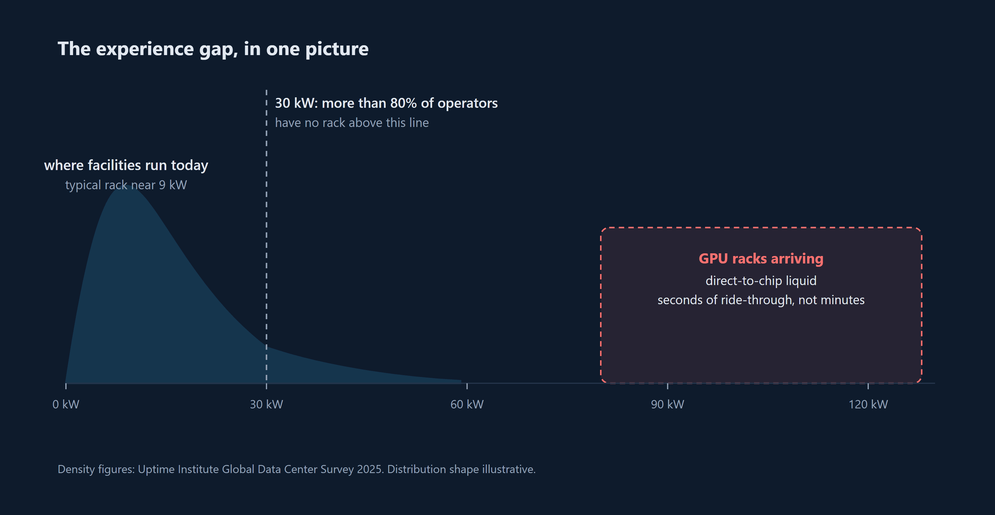
Liquid Cooling Is Arriving Faster Than the Skills to Run It
More than 80 percent of operators have never run a rack above 30 kW, and the typical facility rack sits near 9 kW. The GPU loads arriving now run far hotter, on pumped liquid, with seconds of thermal ride-through instead of minutes. The hardware will arrive on schedule. Here is the four week program that gets the team ready before it does.